|
Ways to Use USB in Embedded Systems
by Yingbo Hu, R&D Embedded Software Engineer
and Ralph Moore, President of Micro Digital
Universal Serial Bus (USB) is a connectivity specification that provides ease of use, expandability, and good performance for the end user. It is one of the most successful interconnects in computer history. Originally released in 1995 for PCs, it now is expanding into use by embedded systems and is replacing older interfaces such as serial and parallel interfaces as the preferred communication link. This article has been written as a tutorial on the many ways that USB can be employed in embedded systems.
Introduction
USB is not a peer-to-peer protocol like Ethernet. One USB device, called the USB host, acts as the master. Other USB devices, called USB devices or USB peripherals, act as slaves. The host initiates all bus transfers. Up to 127 USB devices can be connected to one USB host via up to 6 layers of cascaded hubs. For embedded systems, it is very unusual to have more than one hub. In most cases, one USB device connects directly to one USB host with no hub.
A USB host requires a USB host controller and USB host software. The latter is layered from the bottom up as follows: (1) USB host controller driver, (2) USB host stack, and (3) USB class driver. The first layer controls the USB host controller – i.e. it reads and writes registers in the controller and it transfers data. The second layer implements the USB protocol and thus controls connected USB devices. The third layer is device-aware and communicates with and controls the actual device (e.g. disk drive, HID human interface device, CDC communication device, etc.) One USB host stack can support multiple class drivers, simultaneously. In an embedded system there usually is only one USB host controller.
A USB device requires a USB device controller and USB device software. The latter is layered from the bottom up as follows: (1) USB device controller driver, (2) USB device stack, and (3) USB function driver. The first layer controls the USB device controller – i.e. it reads and writes registers in the controller and it transfers data. The second layer implements the USB protocol and thus communicates with the USB host stack. The third layer communicates with the class driver in the host and provides the actual device control. It makes the embedded unit look like a USB disk drive, HID, serial device, etc. One USB device stack can support more than one function driver simultaneously, through the composite device framework.
A nice feature of USB is it is plug and play, which means that a USB device will be automatically recognized shortly after being connected to a host. Also, cabling is simple: There is an A receptacle/plug pair for the host end and a B receptacle/plug pair for the device end. All hosts and devices adhere to this standard, except On The Go (OTG) devices, which are designed for but not widely used yet in embedded systems.
Example Configurations
Following are examples of how USB can be utilized in the embedded system, for both host and device. Where performance information is given, a “medium performance processor” is assumed to be a 50-80 MHz ARM7 or ColdFire.

Figure 1: PC to Device via USB Serial
Most new PCs and laptops do not provide serial or parallel ports; they have been replaced with USB ports. Hence, connecting a PC to embedded device via its RS232 port is no longer possible. As part of their USB host stacks, popular PC operating systems (Windows, Mac OS, and Linux) include Communication Class Drivers (CDC). As shown in Figure 1, if the embedded device has a Serial/CDC Function Driver then it will look like a serial device to the PC. When it is plugged in, it will be recognized by the PC OS as a serial device, and it will be automatically assigned a COM port number. Then, terminal emulators and other serial applications can communicate with the embedded device without any modification! Hence, we are back to where we started, which, in this case, is a good thing. This use of USB is particularly good for control and transferring serial data. Transfer rates of 800 KB/sec are feasible at full speed and 2500 KB/sec at high speed for medium speed embedded processors.

Figure 2: PC to Device via USB Disk
Another method to connect a PC or laptop to an embedded device is for the embedded device to emulate a USB disk drive. Popular PC operating systems have built-in USB mass storage class drivers that interface their file systems to the USB host stack, as shown on the left side of Figure 2. Adding a mass storage function driver to the embedded device enables it to look like a USB disk drive to the PC. Also shown, as an example, is how a resident flash memory can be accessed as a flash disk via the USB function driver connected to its flash driver. Any other type of storage media could be connected, instead, via its own driver.
When the embedded device is plugged into a PC, it is recognized as a disk drive and automatically assigned a drive letter. Thereafter, files can be dragged and dropped to and from the embedded device as though it were a disk drive. In this example, a PC application could read and write the files on the flash disk. Note that the embedded application uses a local file system, as shown in Figure 2, to access the flash disk, itself. This file system must, of course, be Windows-compatible. An important concept to understand is that within the PC, the PC’s file system is used and the embedded device merely looks like another disk drive to it. This use of USB would be particularly good for uploading acquired data files or downloading new versions of code files.
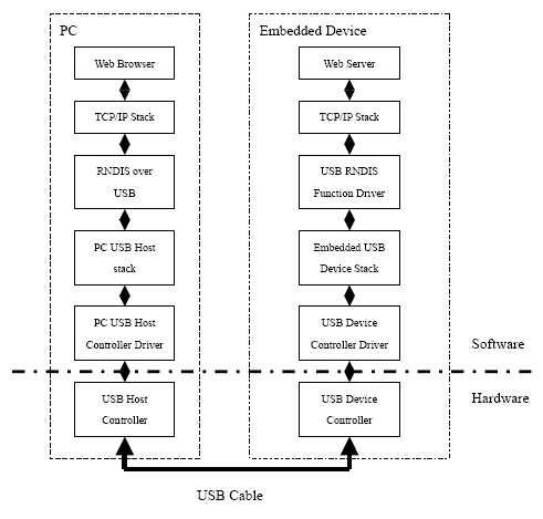
Figure 3: Web Server Access via USB RNDIS
RNDIS (Remote Network Driver Interface Specification) permits emulating Ethernet over USB. It is not part of the USB specification, but some popular PC operating systems, such as Windows and Linux, support it. As shown in Figure 3, adding an RNDIS function driver to an embedded device allows interfacing its USB device stack to its TCP/IP stack that, in turn, connects to its web server. When the embedded device is plugged into a PC, its browser can connect to the web server in the embedded device. Hence, it is possible to use a browser to access an embedded device’s web server, even when there is no Ethernet connection or it is difficult to access. This can be convenient for field troubleshooting or configuration using a laptop. The same information accessed via the network to which the embedded device is connected, can be accessed via USB.
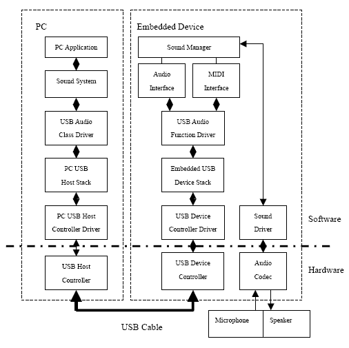
Figure 4: USB Audio Device with MIDI
The USB Audio Class is defined such that if a USB device follows the specification, a PC host will treat it as a sound card. As shown in Figure 4, this is accomplished by adding an audio function driver to the embedded device. This function driver provides both an audio interface and a MIDI (Musical Instrument Digital Interface) interface to a sound manager, which in turn can connect to a microphone, speaker, or other audio gear, such as a musical instrument. Thus audio and MIDI streams can be transferred over a USB link rather than using audio or MIDI cables. This uses the USB isochronous mode of data transfer.
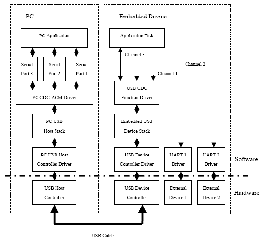
Figure 5: USB Multi-Port Serial Device with UART and Other Connections
In Figure 1 we examined the case of one serial channel over a USB connection. However it is actually possible to run multiple, independent serial channels over one USB connection. This is practical because of the higher speed of USB, as noted in the Figure 1 discussion. Figure 5 shows the block diagram. The CDC ACM class driver in the PC may not be the native driver that comes with the PC OS. A special driver may need to be installed. This driver presents multiple virtual COM ports to the PC application and it multiplexes the corresponding serial channels over the USB connection.
In the embedded device, the USB CDC function driver de-multiplexes the serial channels. Note that, in this example, one channel goes to an application task, which might return certain internal information, and the other two serial channels connect to actual UARTs. The application in the PC can communicate with physical devices, (such as modem, bar code reader, printer, etc.) connected to the UARTs as though they were connected directly to serial ports on the PC (which we know does not actually have serial ports, anymore). The high throughput of USB makes multiple channels feasible. For example, with a medium performance processor and full speed USB, a total bandwidth of 200 KB/sec is achievable. This would support 15 115.2 Kbaud channels, with capacity left over!
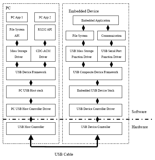
Figure 6: USB Composite Devices
It is actually possible for one USB device to look like multiple USB devices to a USB host, simultaneously. This is made possible by the USB Composite Device Framework, as shown in Figure 6. The USB host (PC in this example) will recognize each USB device within the embedded device and load its corresponding class driver. In Figure 6 the device looks like a USB disk and a serial port. Note that both function drivers are present. This example is a fairly common case that is supported by PC OSs. Many possible combinations are not supported by PC OSs. This particular one would support an application in the PC transferring files and another application allowing an operator to control or configure the embedded device.
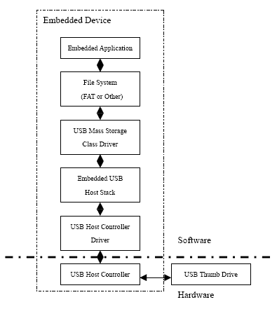
Figure 7: USB Thumb Drive Support
Figure 7 shows how an embedded device can access a USB thumb drive (also called a “USB memory stick”). A mass storage class driver fits between the USB host stack and the local file system in the embedded device. It creates the usual read/write logical address API expected of media drivers. Naturally the file system must be OS-compatible in order to exchange thumb drives with a PC. Thumb drives are commonly used to transfer data from embedded devices to PCs or to update firmware or configuration settings and tables in embedded devices.
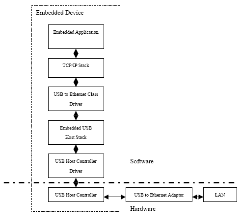
Figure 8: USB to Ethernet
If an embedded device already has USB host capability, it is possible to connect it to a local Ethernet network using a USB to Ethernet adapter. This can be done without adding hardware to the embedded device. Figure 8 shows the software required to do the job. The USB to Ethernet class driver interfaces the USB host stack to a TCP/IP stack in the embedded device. This allows some units to connect to a LAN without the expense of adding Ethernet connectivity to all units. It thus allows greater flexibility in meeting customer requirements and saves redesign.
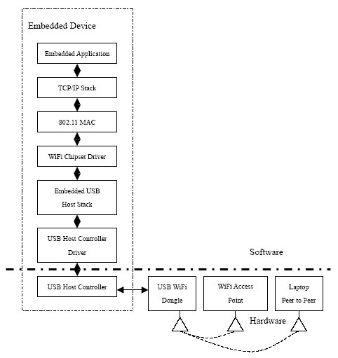
Figure 9: USB to WiFi
Wireless communication is becoming more and more popular. Several vendors are providing USB to WiFi (802.11) chipsets which enable systems having USB host ports to add wireless connectivity. These chipsets are commercially available in what are called “WiFi dongles” or “WiFi keys” and are generally inexpensive. Figure 9 shows the software needed in the embedded device. The 802.11 Media Access Controller provides an Ethernet-like interface to the local TCP/IP stack and controls the 802.11 controller in the WiFi chipset. The WiFi chipset driver controls the USB interface in the chipset. For security, 802.11 MAC also provides WEP (Wired Equivalency Privacy) or WPA (WiFi Protected Access).
Like the USB to Ethernet capability shown in Figure 8, this feature can be added to only some embedded units, as required. It is very useful in the field when a wired connection is not available or too expensive. Transfer rates of 200 KB/sec are typical for medium performance processors.

Figure 10: USB Modem Access
If an embedded device already has USB host capability, adding a USB CDC-ACM class driver can be used to add dialup modem capability to the system. This is shown in Figure 10. No hardware change is necessary. USB modems are available that connect to phone lines in the PSTN system. Some cell phones that have a USB modem interface can be used to connect wirelessly. Hence, this can be a flexible option for connecting to an embedded device. It is especially useful when the dialup communication is only needed occasionally. Also, one USB modem can be shared between multiple devices to save the cost of adding modem hardware. Dialup connections are very useful for long distance communication.

Figure 11: Connection to Multiple Sensors and Actuators
Figure 11 shows how an external hub can be used to connect an embedded control unit to multiple sensors and actuators. In this diagram, it is assumed that the sensors are serial devices. They are handled by a serial class driver. The actuators are assumed to be custom devices requiring custom class drivers. A well-structured USB host stack permits easily adding custom class drivers. Standard USB peripherals, such as printers and bar-code readers could also be added. They would be supported by standard class drivers. For example a keyboard or joystick would be supported by an HID class driver. A gaming machine is a good example of a unit incorporating custom sensors and actuators and standard USB peripherals.
Conclusion
USB usage in embedded systems so far has been largely centered on dealing with the loss of serial and parallel ports on PCs and laptops, the loss of parallel interface printers, and with capitalizing on the low cost and convenience of USB thumb drives for transporting information. However, as we hope this article has shown, USB offers many other capabilities that are available to solve other problems in the embedded space. We expect to see these uses grow in the future.
Micro Digital’s software supports all of the configurations described in this article.
Yingbo Hu is the lead developer of smxUSBD, smxUSBH, and smxWiFi, as well as smxFS and smxFFS products of Micro Digital Inc. He specializes in writing device drivers for embedded peripherals, such as USB and flash, and he has 11 years experience developing real-time embedded software. He graduated with a Masters Degree from Beijing University of Aeronautics and Astronautics.
Ralph Moore is the current President and founder of Micro Digital, Inc. He graduated from Caltech with a Bachelors degree in physics long before the first “embedded system” or even the first integrated circuit. He has watched our industry develop with amazement. Mr. Moore is also the architect of the smx® real time multitasking kernel.
If you would like a reprint of this article, email info@smxrtos.com and give your US address.
For More Information
- smxUSBD Datasheet
- smxUSBH Datasheet
- smxUSBO Datasheet
- smxWiFi Datasheet
- smxNS Datasheet
- smxFS Datasheet
- smxFFS Datasheet
Copyright © 2008-2009 by Micro Digital, Inc. All rights reserved.
smx is a registered trademark of Micro Digital Inc. smx product names are trademarks of Micro Digital Inc.
2/12/09
back to White Papers page
|