
MPU Operation
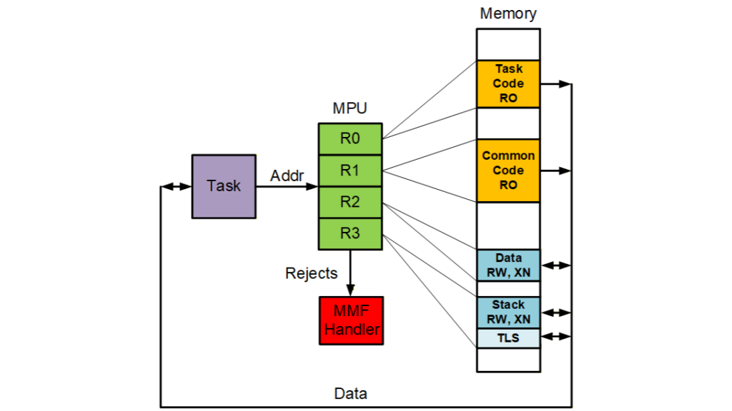
The above figure shows the basic operation of a memory protection unit (MPU). For simplicity, this MPU has only four regions, but most actual MPUs have 8 regions. In this case, the regions are task code, common code, data, and the stack with task local storage (TLS) below it. Each region has an address range and attributes such as read-only (RO), read/write (RW), and execute never (XN). If the address presented by a task is within one of the regions and satisfies the attributes of that region, it is allowed to access memory. If not, a memory manage fault (MMF) occurs, the MMF Handler runs, and the task is normally stopped.
Code samples that follow are for the Cortex-v7M architecture and the IAR EWARM tool suite. Code for the Cortex-v8M architecture is similar.
Memory Protection Arrays
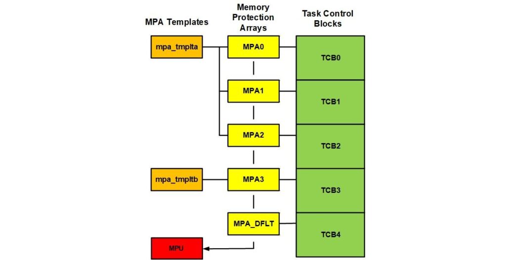
Every task has a memory protection array (MPA). When a task is dispatched, its MPA is loaded into the MPU. The figure below shows the relationship between Task Control Blocks (TCBs), Memory Protection Arrays (MPAs), and MPA templates. Note that an MPA template might apply to a single MPA and task or it might be shared between MPAs and their tasks. In the latter case, the tasks would normally be in the same partition. There is also a default MPA that does not require a template. It is used when no MPA has been created for a task.
The MPA for a task is created after the task:

ut2a, a umode task, is first created, then its MPA is created from the mpa_tmplt_ut2a template, which looks like:

Each line in the template represents RDAR, RASR, and name. The first two are the MPU registers that are loaded into the specified MPU slot (i.e. 0 – 3), the third is used to identify regions during debugging. Macros, such as RGN and RA, simplify defining the MPU registers. This template is loaded into the first four MPA regions, the next three are cleared, and the task stack region is loaded into MPA[7]. The ucom data and code regions are common to all umode tasks. The ut2a data and code regions are specific to the ut2a task. Other regions might be needed by some tasks, such as IO regions.
Defining Regions
Regions are composed of sections, which are defined in the code using pragmas as follows:

Similarly for data:

Sections having the same name that are scattered throughout the code are merged into single sections by the linker. If all code in a file belongs in related sections then it is possible to put
#pragma section_prefix = ".ut2a" /* ut2a sections */at the top of the file to avoid using the other pragmas. The next step is to define the linker command file.
Linker Command File
Sections are used to define region blocks in the linker command file. For example:

Note that the region sizes are powers of two, as required by the v7 MPU. ut2a_code and ut2a_data are region blocks that become MPU regions. The actual region block sizes are the nearest larger of 5/8, 6/8, 7/8, or 1 times the region size. This utilizes subregion disables for the last 3, 2, 1, or 0 subregions, respectively. Note that the region blocks are aligned on region sizes. The region blocks are placed in ROM and SRAM, respectively, at the end of the linker command file:

Conclusion
This has been a quick overview of MPU basics. The next part of this article will cover more advanced topics such as static slots, dynamic slots, auxiliary slots, slot swapping, stack regions, and multi-task partition regions. Code for foregoing can be seen in mpa7.c, cpsrvr.c, and stm32746g_app_mpu.icf at www.github.com/Micro-Digital/SecureSMX.