
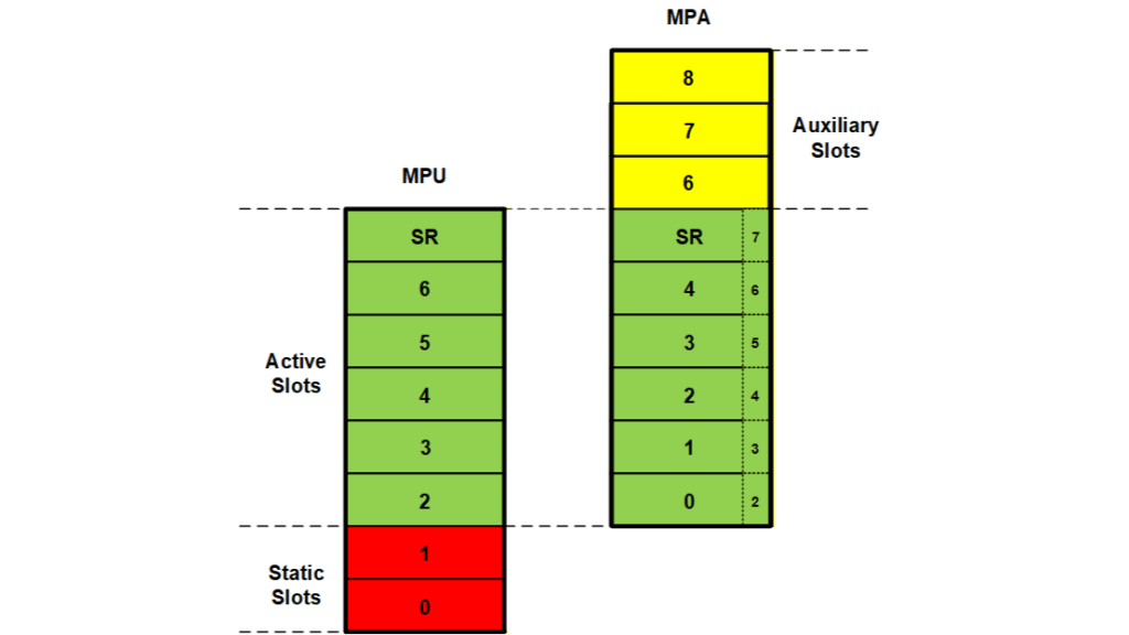
Basic MPU control was discussed in Part 1 of this series [ref 1]. In this part we will examine ways to work around MPU problems and to improve MPU control.
Base Region
To handle exceptions and interrupts, the Cortex-M Base Region (BR) can be turned on in unprivileged mode (umode), where it has no effect. When an exception or interrupt switches the processor into handler mode (hmode), BR becomes active and allows accessing all implemented memory, regardless of MPU contents. BR is normally turned off in privileged mode (pmode) so that the MPU can be used to isolate pmode tasks.
Static Slots
Static MPU slots are slots that are loaded once, usually during initialization. They are not reloaded on task switches, thus reducing task switching time. Static slots are normally the low-numbered slots, starting at 0, as shown in the diagram. For example, ucom_data and ucom_code, the common umode regions, might be loaded into MPU[0] and MPU[1], thus making them available to all tasks.
Another possible use for static slots, is sys_data and sys_code, the system pmode regions[1]:

Where sys_data and sys_code contain all variables and code necessary to execute interrupts and exceptions. PDATARW and PCODE regions can be accessed only by privileged code. In this case, BR can be set permanently off. sys_data and sys_code might limit malware access to less memory than BR. However, the MPU is accessible in hmode, regardless of MPU contents, and thus malware can easily turn it off. Thus, using static slots for sys_data and sys_code provides little added security. On the downside, using two slots for static regions leaves only enough slots for 6 active regions, which may not be enough for all partitions.
Dynamic Regions
A template usually contains fixed regions that are defined at compile time. However, it can also contain dynamic regions. A dynamic region has a means to indicate that it is not a fixed region and it has a pointer to where its region information is stored. When an MPA is created, that information is loaded into the dynamic slot in the MPA. The advantage of a dynamic region is that it can be created, on-the-fly, to be the right size, such as when allocating a block from a heap. This allows adjusting to different installation or operational requirements while running. It is important to note that MPAs, and hence dynamic regions, can be created only in pmode and thus only by trusted software. A hacker who has penetrated a umode partition cannot create dynamic regions other than via system calls to create pblocks and pmsgs [ref 2].
Auxiliary Regions
Auxiliary regions offer a solution for tasks that need more than 8 regions. As shown in the figure below, auxiliary regions in an MPA are above the active regions that are loaded into the MPU by a task switch. They contain regions that can be swapped with active regions, as needed:
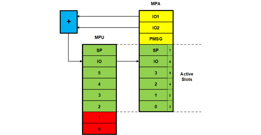
In the above diagram, either IO1 or IO2 can be switched into IO, as needed. One might wonder how to know when the other region is needed. That’s simple – you get an MMF! IO regions are shown here because they are usually ae the culprits that cause 8 slots to be exceeded. For example, the LED partition in the SecureSMX framework requires 3 IO regions: GPIOI, I2C1, and RCC. This would use up all remaining slots in the example shown in Part 1, leaving no room for any more regions.
A pmsg auxiliary slot is also shown above. This is a special case involving the v8 MPU, which does not allow regions to overlap. For a portal [ref 2], if a pmsg data region comes from a data region already in the MPU, loading the pmsg region into an active slot would cause an MMF, when the overlapped memory was accessed. This MMF is confusing because an MMF usually means that the access is not in any MPU region rather than that it is in two MPU regions. The auxiliary slot avoids this by providing a safe place to park the pmsg region until the server releases it. (The pmsg region is not needed since its data block is already in a data region in the MPU.)
Child Tasks
For those queasy about slot swapping, child tasks may offer a more attractive alternative:
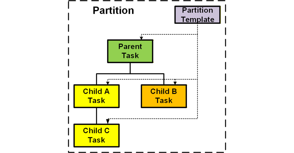
The idea is that the parent task spawns child tasks, which may spawn their own child tasks, all in the same partition. The partition has a single MPA template and each task is assigned regions from it when the task’s MPA is created:
mp_MPACreate(TCB_PTR task, MPA* tmpl, u32 tmsk, u32 mpasz);Here, task is one of the tasks, tmsk is a bit mask that picks the needed regions in the template, tmpl, for the MPA being created for task, and mpasz is the size of the MPA. In the foregoing IO example, the LED child task would be given the IO regions it needs. It would not need the ucom_code and ucom_data regions. The parent task, on the other hand would need the ucom regions, but would not need the IO regions. Thus everybody is happy and region swapping is not necessary.
Stack Regions
An optimum approach is to allocate a task’s stack from a heap when the task is created. (Of course, this requires a heap, like eheap, that can allocate a block of the right size and alignment required by the MPU.) In addition, for a v7M MPU, it must set subregion disables to achieve the best fit. An alternate approach is to use static stacks or stack pools in which the stacks are already properly sized and aligned. The heap approach offers more flexibility, but either works fine for security. In both cases, the stack region has RW (Read/Write) and XN (eXecute Never) attributes. XN is important because it defeats a number of possible hacks.
As a consequence of using a stack region, stack overflows and attempts to execute from the stack cause immediate MMFs. The worst a hacker can do is to wreck the stack and possibly the Task Local Storage (TLS) below it for the task he has hacked. He cannot damage other stacks nor execute malware from the stack he has hacked. For best security, the task stack region is put into the top MPU slot. This is because for v7M, the attributes of the higher number slot prevails when regions overlap. This insures that the XN attribute will not be overridden by another data region if it overlaps the stack region. v8M does not permit region overlaps, so this is not a factor for it, but the top MPU slot is still used, for consistency.
When taskA is created:
taskA = TaskCreate(taskA_main, TP2, SSZ, UMODE | hn, "taskA");
MPACreate(taskA, (MPA*&mpa_tmplt_taskA, 0xF, 4);
with a permanent stack of SSZ bytes, its stack is allocated from heap hn and its region is created and stored in the taskA’s TCB. When the taskA MPA is created, the stack region is loaded from the TCB into MPA[7]. If, instead, the task uses a temporary stack from the stack pool (SSZ == 0), its region is created and loaded into MPA[7] and MPU[7] when the task is dispatched.
Cortex-v8M presents a problem due to not allowing regions to overlap. In this case, it is recommended that task stacks come from a heap, block pool, or static blocks in a region dedicated to task stacks. Protected messages (pmsgs) and blocks (pblocks), which have the same overlap problem, should also come from that region.
Cortex-v8M has a new feature, PSPLIM (process stack pointer limit) to detect task stack overflows. This can be used instead of a separate stack region to save an MPU slot. However, it does not protect against stack block underflow. It also does not protect against execution of code in the task stack, unless the task stack comes from a data region with the XN attribute.
Conclusion
This has been a review of techniques to improve MPU setup and operation. Code for these can be seen in mpa7.c, mpa8.c, xmpu.c, and xgo.c at www.github.com/Micro-Digital/SecureSMX. The next part of this series will review methods to improve memory efficiency for v7 MPUs.
References
1. “Memory Protection Unit, Part 1: Basics”, Ralph Moore, LinkedIn, Feb 2026.
2. “Portals Isolate Partitions”, Ralph Moore, LinkedIn, Feb 2026.
Notes
[1] See Part 1 for description of MPA templates.