
Introduction
High security for IoT devices is about to become mandatory in Europe [Ref 1]. Hence, it is becoming important to pick an RTOS that supports high security. Two leading contenders are Zephyr and SecureSMX (SSMX). This article explores the strengths and weaknesses of each.
Zephyr supports a wide variety of processor architectures, whereas SSMX supports only the Cortex-M architecture. So this comparison is limited to implementations for the Cortex-M architecture, which is used in nearly 70% of microcontrollers being shipped today.
Cortex-M processors operate in one of three modes:

Both RTOSs rely on memory protection units (MPUs) to provide isolation for security. Most MPUs have 8 slots. Larger or smaller MPUs exit, but 8 is by far the most common and is assumed for this article.
Zephyr MPU Control
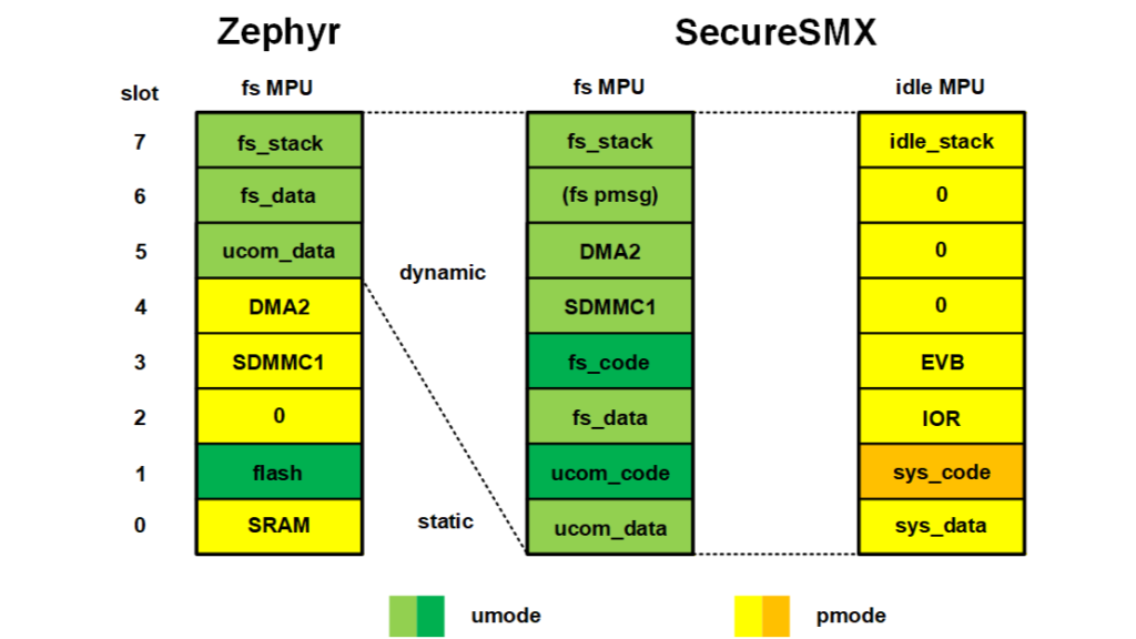
A Zephyr domain consists of one or more user mode data regions and one or more member threads[1]. A region[2] consists of a starting address, a size, and attributes such read write, RW, read only, RO, and execute never, XN. Domains exist only in user mode. The diagram illustrates a typical MPU structure for Zephyr, when the FatFs thread is running.
The static regions are loaded during initialization. At a minimum, there is one privileged region for all of SRAM with RW and XN attributes and there is one flash region with RO and X attributes for all code and read-only data. It is accessible from both privileged and user modes. Also shown are SDMMC1 and DMA2, which are IO regions needed by the SD flash driver for FatFs. These must be static regions since Zephyr requires device drivers to be in privileged mode.
This diagram is just an example to show how static regions might be used. In an actual system, all IO regions might be grouped into a single IO region to save one MPU slot or the Background Region (BR) might be turned on to save two MPU slots.
The dynamic regions are reloaded whenever a thread switch occurs. Each user mode thread has its own stack and at least one domain. The domain shown in the diagram consists of two regions. The first is the data region for domain A. This is shared between all threads in domain A. The second is a shared data region between domains A and B. It could be a small region used to exchange data between the domains. Each region requires an MPU slot.
Domains contain only user mode data. They are created at runtime from partitions[3]. Partitions are statically defined as follows:
K_MEM_PARTITION_DEFINE(name, start, size, attr)where name is the name of the partition, start is its starting address, size is its size in bytes, and attr are its attributes such as RW, RO, XN, etc. Partitions are stored in flash.
A domain is created by:
k_mem_domain_init(domain, num_parts, parts)where domain is its handle, and num_parts is the number of slots in parts[], which is an array of partition addresses. In the above example, num_parts = 2. Domains are stored in SRAM.
Partitions are dynamically assigned to domains at runtime:
k_mem_domain_add_partition(domain, name)This puts the partition, name, into the next available slot the parts array in domain.
Threads start in a default domain and can then be assigned to custom domains with:
k_mem_domain_add_thread(domain, thread)Multiple threads can belong to a domain and a thread can belong to multiple domains.
SSMX MPU Control
The diagram illustrates typical MPU structures for a umode task (fs) and a pmode task (idle). When a task is dispatched, its memory protection array (MPA) is loaded into the MPU. When a task is first created, it is assigned a default MPA, which normally covers all accessible memory. Using the default MPA allows legacy tasks to run as is. For other tasks, custom MPAs can be created with:
mp_MPACreate(task, tmp, tmsk, mpasz)where task is the handle of the task using the MPA, tmp is the MPA template pointer, tmsk selects regions from the MPA template, and mpasz is the size of the MPA. MPAs are allocated from the main heap. The resulting MPA pointer, tmp, and mpasz are stored in the task’s TCB. SSMX also supports static MPU regions, in which case, mpasz would normally be less than MPU size. MPA templates are defined statically and stored in flash. The MPA template for the FatFs task is as follows:
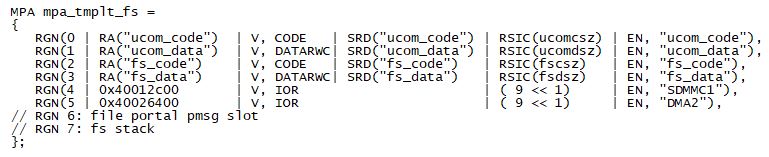
Regions above a template, such as RGN 6 & 7, above, are filled with 0s. RGN 6 is a runtime slot for the region of a protected message (pmsg) when received by the FatFs portal. RGN 7 is reserved for the fs stack region. Background region, BR, is on for umode, but has no effect. If an exception or interrupt occurs while in umode the processor switches to hmode and BR becomes effective.
The template for the idle task is as follows:

This is a pmode template. Since BR is off for pmode, sys_code and sys_data must allow access to all code and data needed by exceptions and ISRs, as well as by system services. sys_code and sys_data must be in all pmode MPAs.
Templates are normally defined to have all regions that a partition requires, which may exceed the MPU size. There are two ways this can be delt with:
- Region swapping. A task’s MPA can be larger than the MPU in order to store additional regions that are not in the MPU. When required by the next section of code, a needed region can be swapped into the MPU in place of an unneeded region that is swapped out,
- Child tasks. When a parent task spawns a child task, the child task’s MPA is loaded with only the regions that the child task needs. Other tasks in a partition may also select only the regions they need from the partition template. Thus, template regions can be spread among several tasks thereby staying below the MPU slot limitation. This is particularly helpful for dealing with the IO regions of device drivers – sometimes as many as three IO regions are required by a single device driver and a system might have multiple devices.
Tasks can share MPAs with other tasks and they can change MPAs, while running.
A developer has the option to create custom MPAs for legacy pmode tasks. Although this does not increase security, per se, it has two advantages:
- It improves the reliability of legacy code by revealing latent bugs and vulnerabilities, such as wild pointers, stack overflows, and buffer overflows that trigger Memory Manage Faults (MMFs). The MMF becomes a new tool to find latent bugs in legacy code.
- It facilitates incremental security improvement of existing firmware. For example, a legacy network stack could first be given a custom MPA and put into a partition, while still in pmode, where debugging is easier, then moved into umode after it is working well.
Why Protect Code?
Two main reasons why code needs to be protected as well as data are:
- If malware breaches a task that has access to all code and ro data, then it can then exfiltrate passwords, keys, proprietary code, and other secret information.
- If malware executes code outside of its domain a Memory Manage Fault (MMF) should occur due to the code accessing data outside of its domain. It is hoped that developers understand this security premise. What if they don’t? Breaches often come through cracks that no one thought were important (except hackers!).
- Unprotected code can be downloaded and studied by hackers in order to find vulnerabilities.
In addition, partitions where both code and data are isolated can often be updated without stopping the system. This is possible because internal addresses are hidden behind partition portals so that code outside of the partition does not see them. In many cases, stopping a functioning embedded system is so expensive that installing security patches is often postponed or never done.
Conclusion
Embedded systems are emerging into a new era where device security will be as important as device features. Consequently, it is desirable to pick an RTOS now that can achieve a high security level for new projects and iterative security improvement for existing products. The SecureSMX RTOS fulfills these needs. It is available under a dual GPL/commercial license. Full source code and documentation are available at: www.github.com/Micro-Digital/SecureSMX.
References
- “The Logic of Isolated Firmware Partitions” Ralph Moore, LinkedIn, July 2026.
Notes
[1] The terms threads and tasks are interchangeable.
[2] Zephyr uses the term partition, but region is the preferred term for Cortex-M and so is used in most places herein.
[3] partition, instead of region, is being used here for consistency with the code that follows.